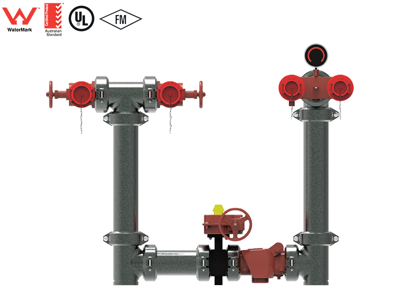
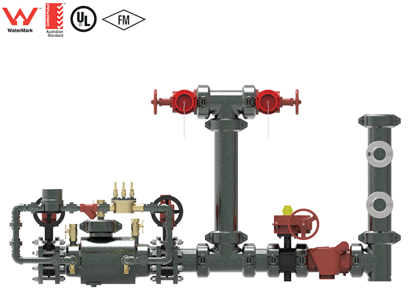
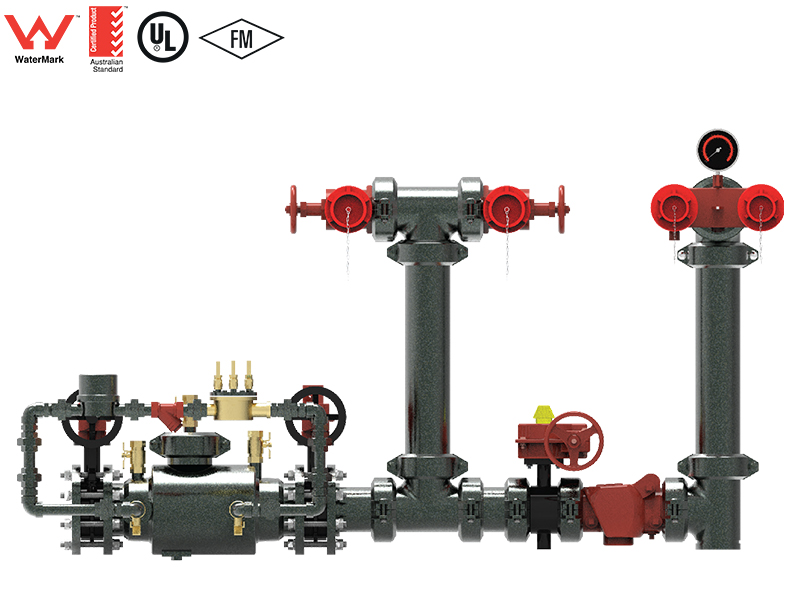
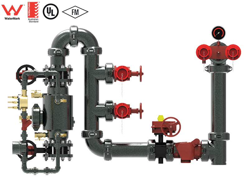
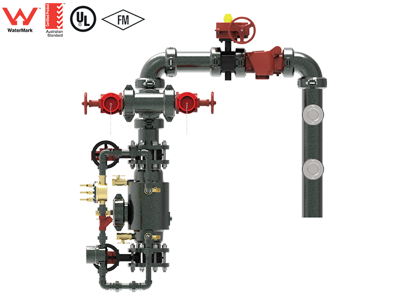
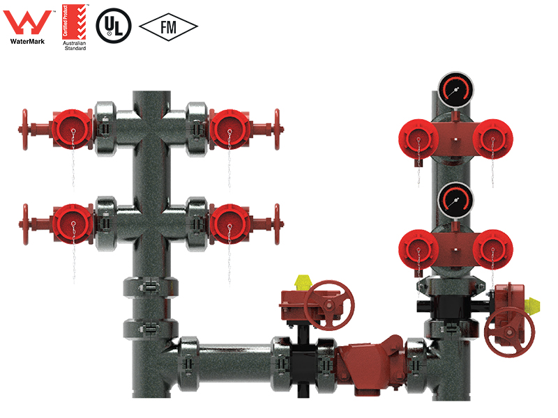
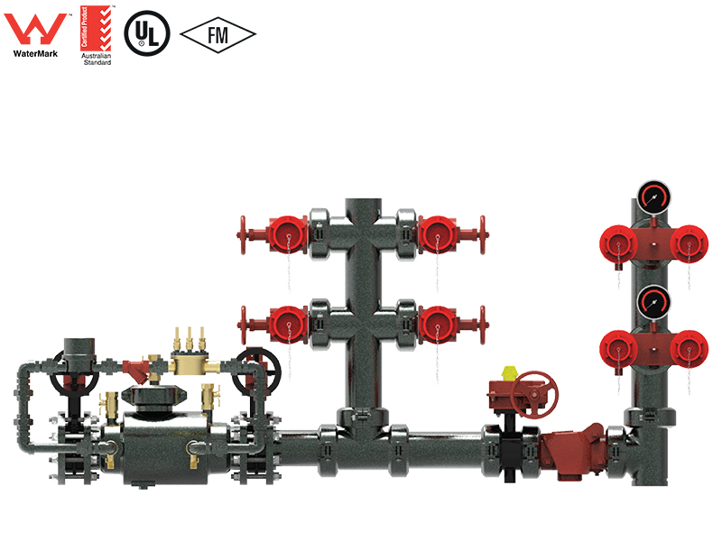
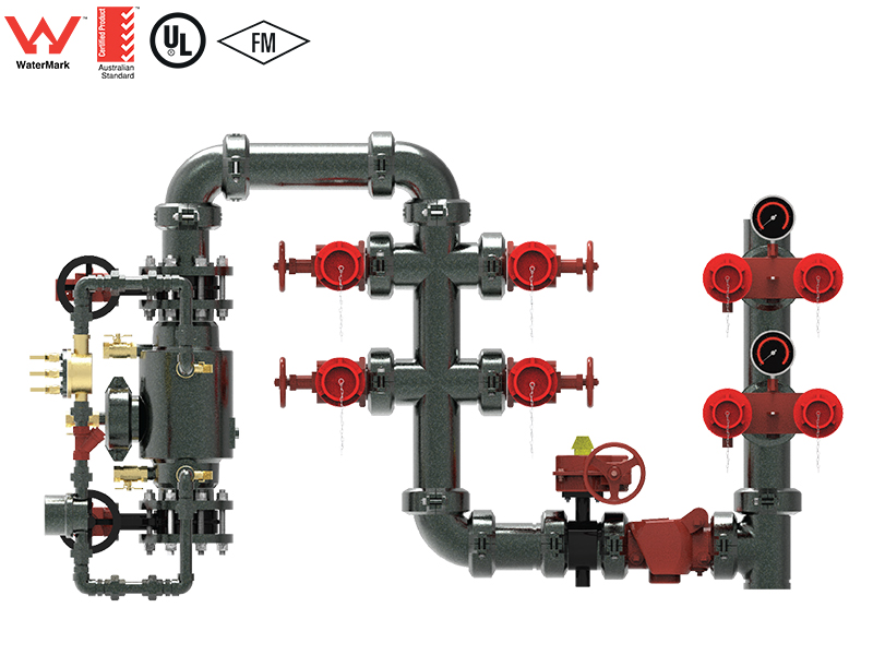
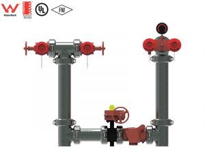
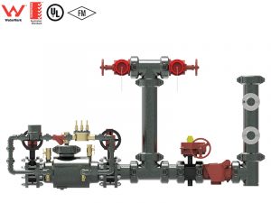
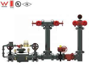
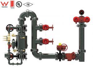
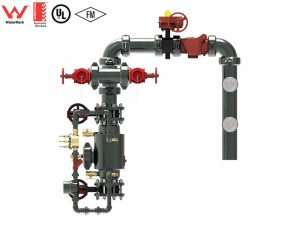
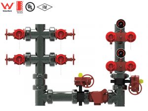
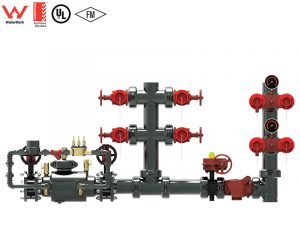
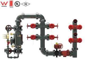
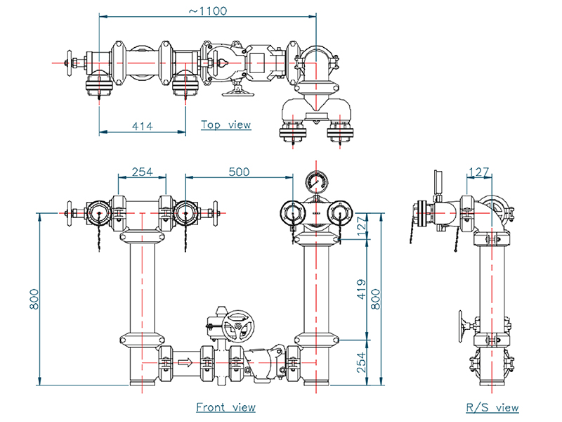
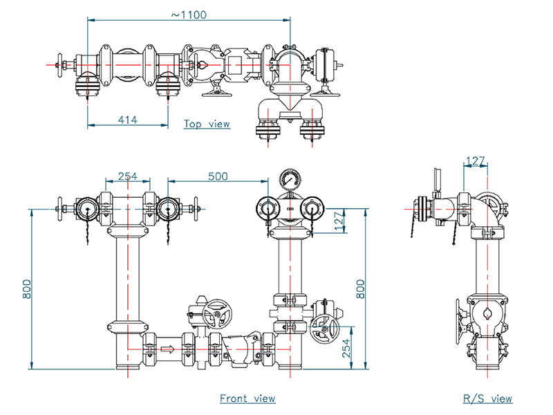
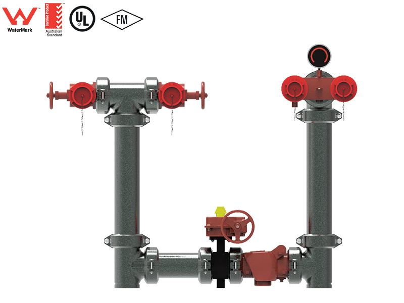
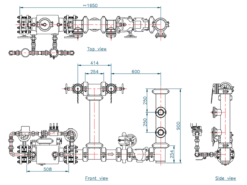
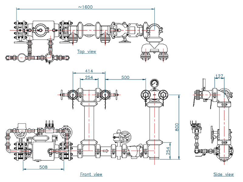
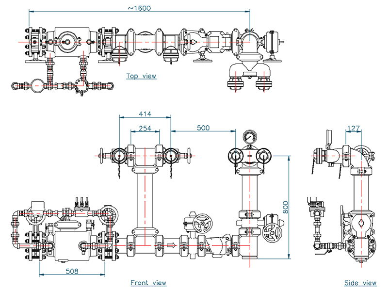
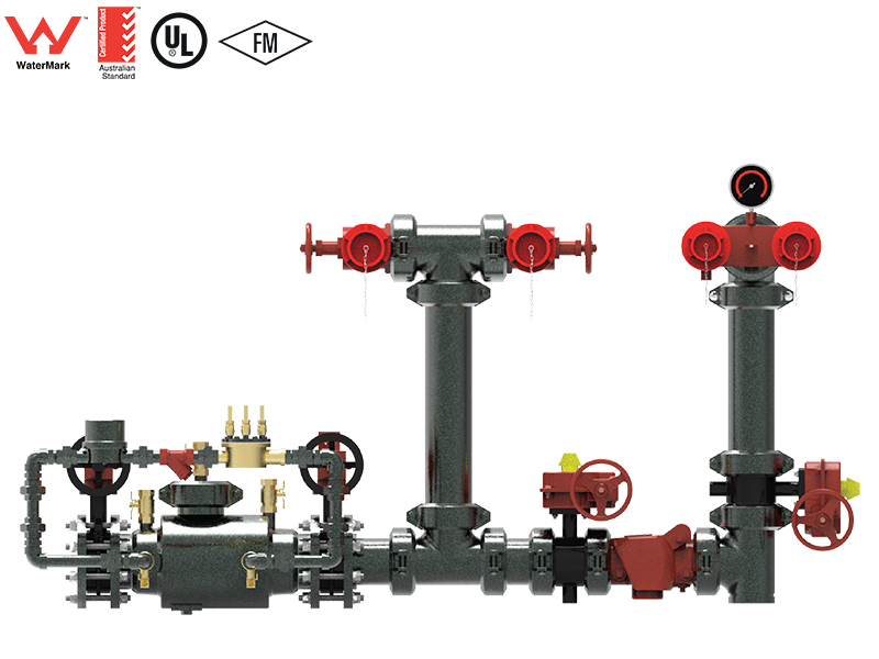
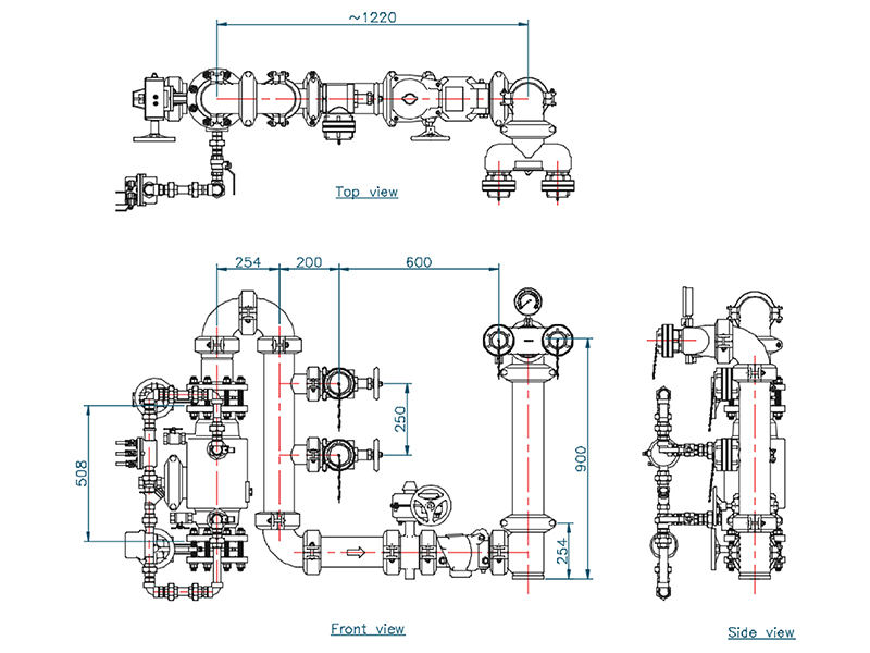
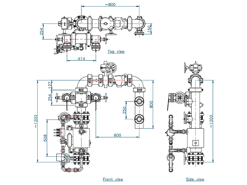
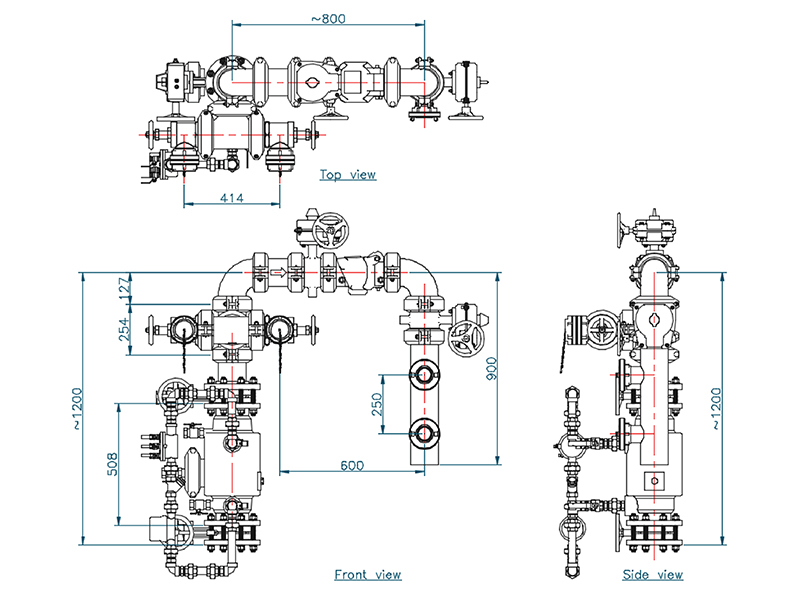
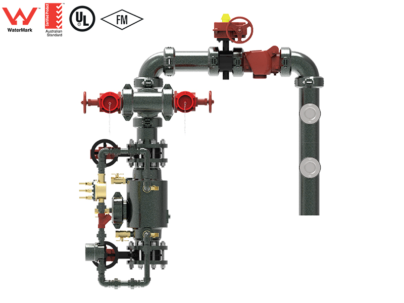
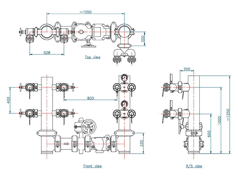
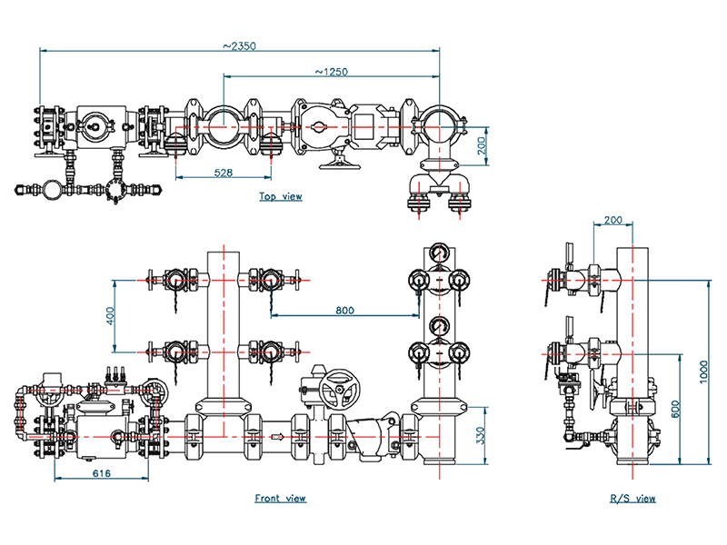
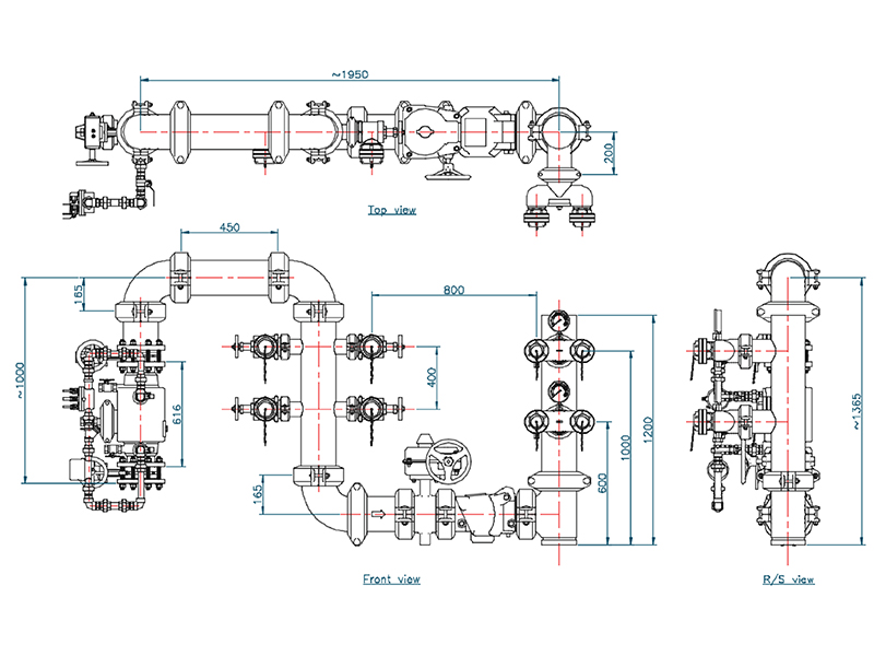
Fire brigade booster assemblies are manufactured in compliance to the requirements of AS 2419.1 standard. Fire brigade booster assemblies fitted to fire hydrants systems are confirming to the requirements of AS 2419.3 and the hose couplings are compatible with those used by the fire brigade serving the area.
FIRE BRIGADE BOOSTER ASSEMBLY CONSISTS OF BELOW COMPONENTS AND CAN BE SUPPLIED WITH DIFFERENT VARIANTS.
- Booster valves.
- Hydrant valves.
- Gate valves OS&Y / NRS.
- Butterfly valves.
- Back flow prevention devices.
- Grooved fittings.
WHEN AND WHERE BOOSTER ASSEMBLY IS REQUIRED
- A fire brigade booster assemblies are designed to install with each hydrant system where —
- Internal fire hydrants are installed.
- External on-site fire hydrants are installed more than 20M from a fire brigade pumping appliance hardstand.
- More than 6 external on-site above ground fire hydrants are installed.
- A pumper is installed.
- On-site storage tanks are installed or
- More than one external on site fire hydrant is required to serve a building where the floor area of any fire compartment is greater than 2000 m2
WHILE ORDERING, PLEASE SPECIFY THE CONNECTION TYPE & VALVE REQUIREMENT.
- LH / RH entry.
- Gate valve or Butterfly valve.
FIRE BRIGADE BOOSTER ASSEMBLY ARRANGEMENT
Feed fire hydrants shall be installed on-site adjacent to booster inlet connections within the following limitations:
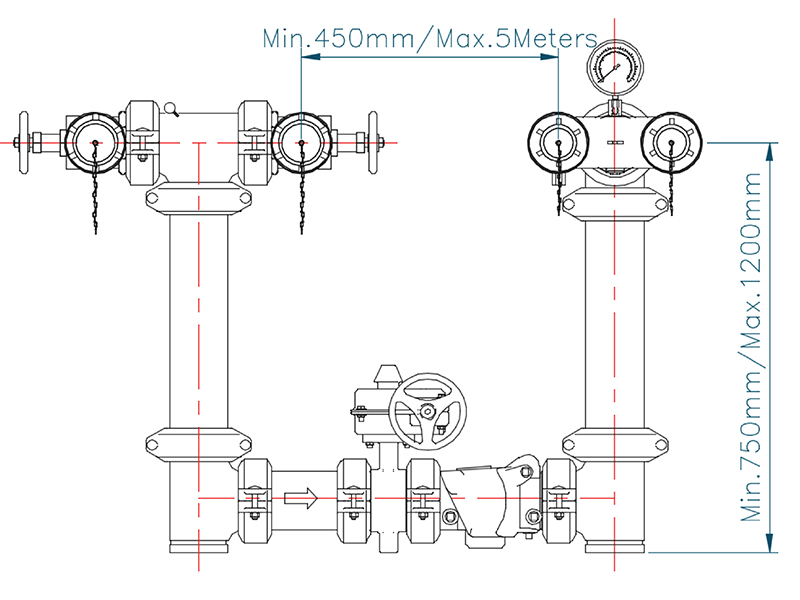
- The center distance between any feed fire hydrant and the closest fire brigade booster inlet shall be not less than 450mm and not more than 5 m.
- The position of feed fire hydrant and fire brigade booster inlet connections shall be such that, when all inlets and outlets have hoses connected, one hose shall not cause interference with another hose.
- The height of the feed fire hydrant outlets and the fire brigade booster inlet connections shall be not less than 750mm or more than 1200mm above the floor or standing surface in front of the fire brigade booster assembly.
TYPICAL ARRANGEMENT
